With the wings on the fuselage I got the flaps onto the wings so I could fabricate the flap pushrods. I started by cutting the pushrod stock to length. I then tapped both ends of the rods for 1/4-28 rod-end bearings. The plans call to use a CM-4S bearing.
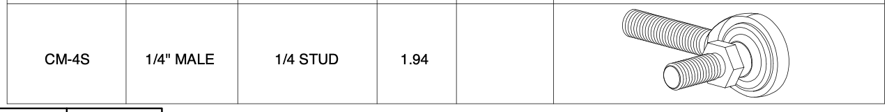
The problem with this is that because it’s an integrated ball into the bearing, there is no way to prevent this from backing out. The instructions call for locktite to hold it in. I will be changing this out to a CM-4M rod-end bearing with a through bolt that can be safety wired. Its much more secure and safe this way.
But while those parts are on order, I still used the default part to do the initial fitting. I installed it onto the flap and then checked the alignment with the bottom of the fuselage. I then cut the hole in the fuselage that the pushrod passes through
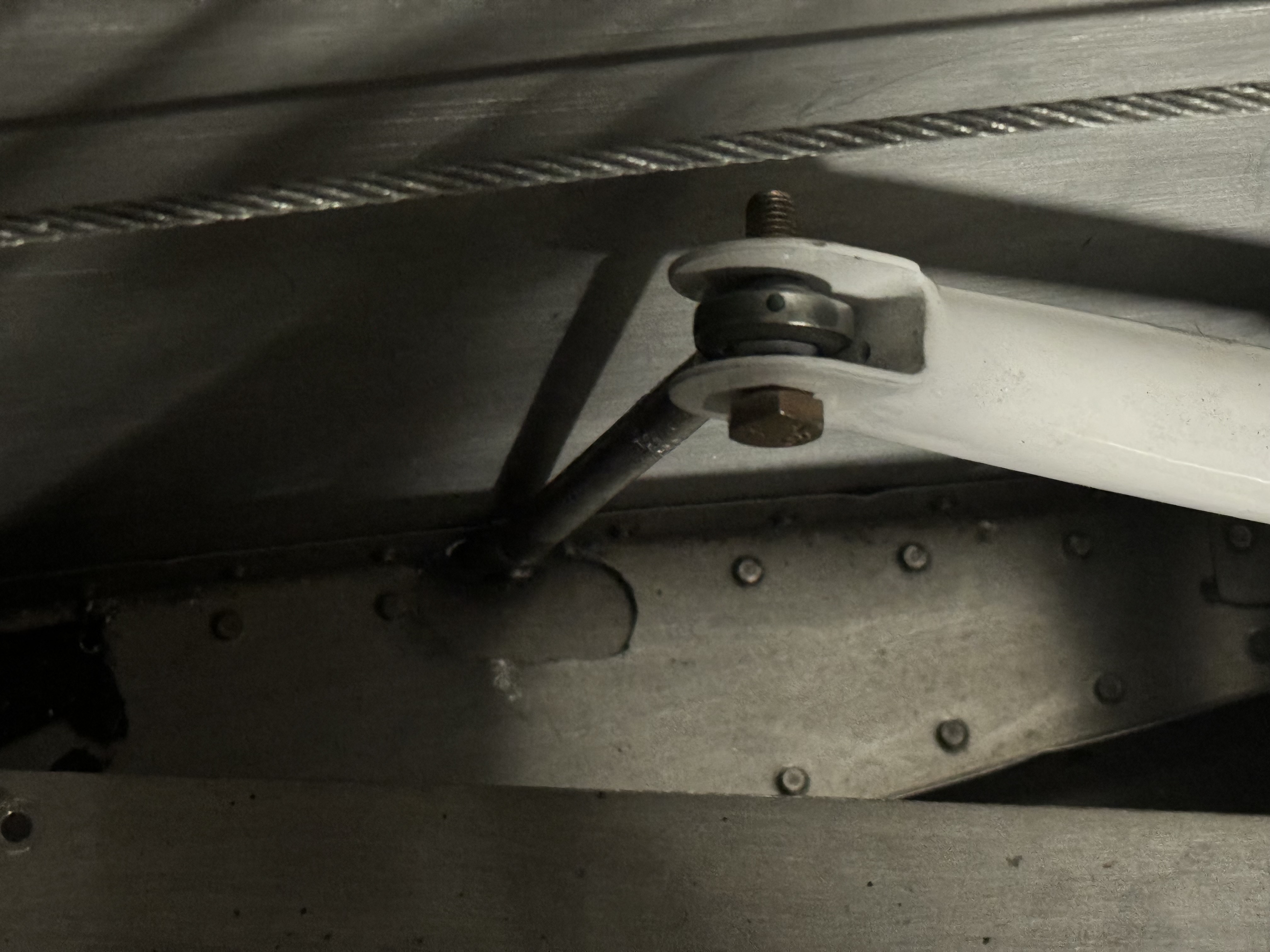
When I installed the bearing into the flap I did not put any spacers, but when I put the update rod end bearing I will be centering the bearing so its not rubbing against the side of the fuselage.
With both flaps on the plane, and aligned I was able to test the deflection of both flaps. Luckily everything was symmetric and the full flap deflection was 45deg. This is above the minimum of 40deg for the RV-7.
With the flaps installed, I then began the aileron aligning. I first began by ensuring the vertical-ness of the control sticks in the plane. When I initially aligned the pilots stick, the copilot stick was inboard by about 6deg. So I adjusted the connecting pushrod so that both sticks were perfectly aligned. It’s hard to see in the pic below, but it says 89.7°, which is close enough for me.
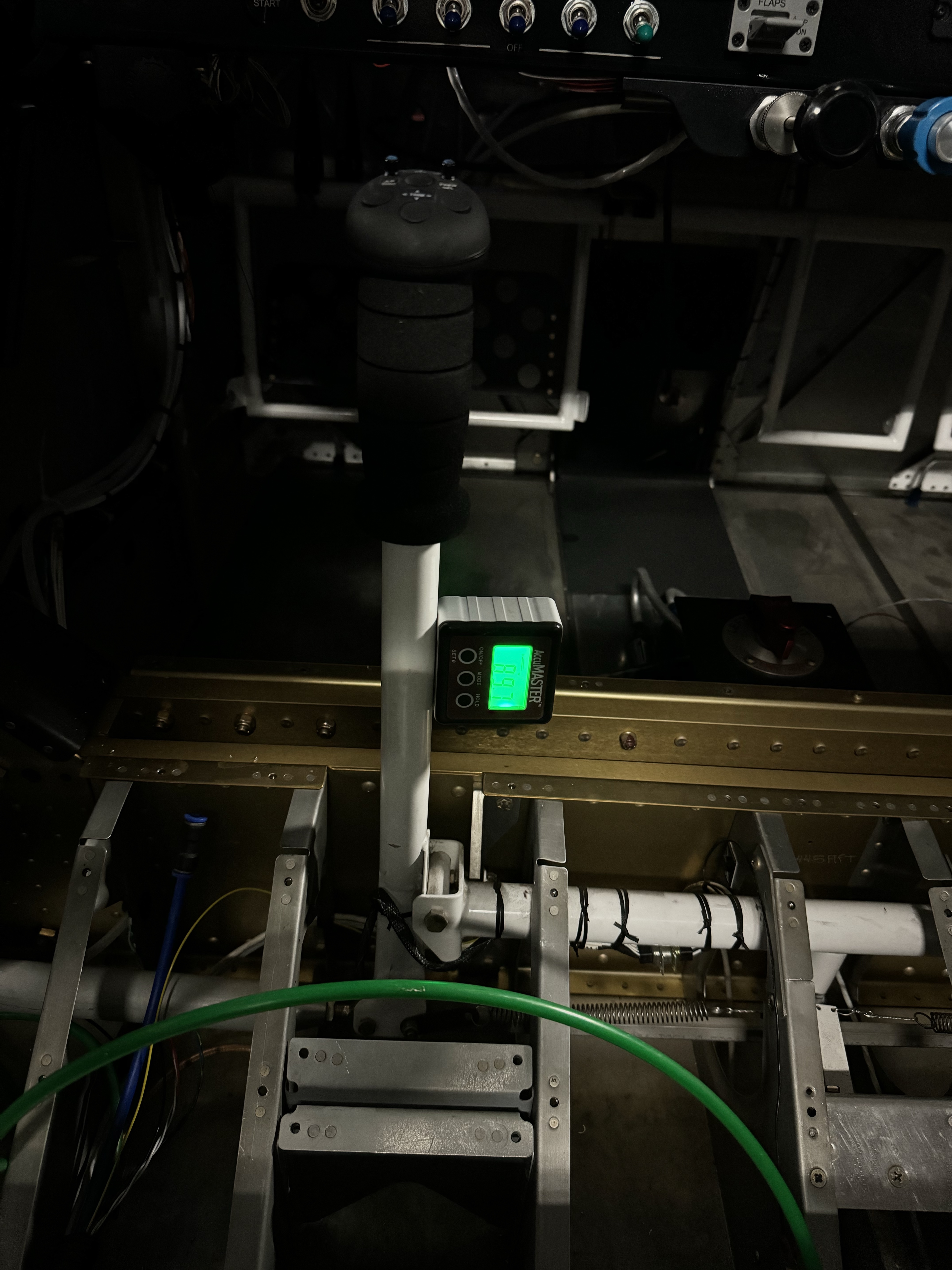
I used a long straight edge to align the aileron with the tooling holes on the outboard rib of the wing (per the instructions) and then ensure that it was aligned with the flaps. I then used the aileron alignment tool to ensure the bellcrank-to-aileron pushrod was the right length, and then, with the control sticks in the vertical position I adjusted the main pushrod. Once the left aileron was adjusted I did the same for the right side. Everything was perfectly aligned to within 0.1deg when comparing everything.


I also got the lower fuselage skins drilled to the wing skins. This has to be done now so that I can remove the wings and install all the nutplates. I also temporarily installed the wing root fairings to drill those as well. They will also be attached with screws through nutplates.
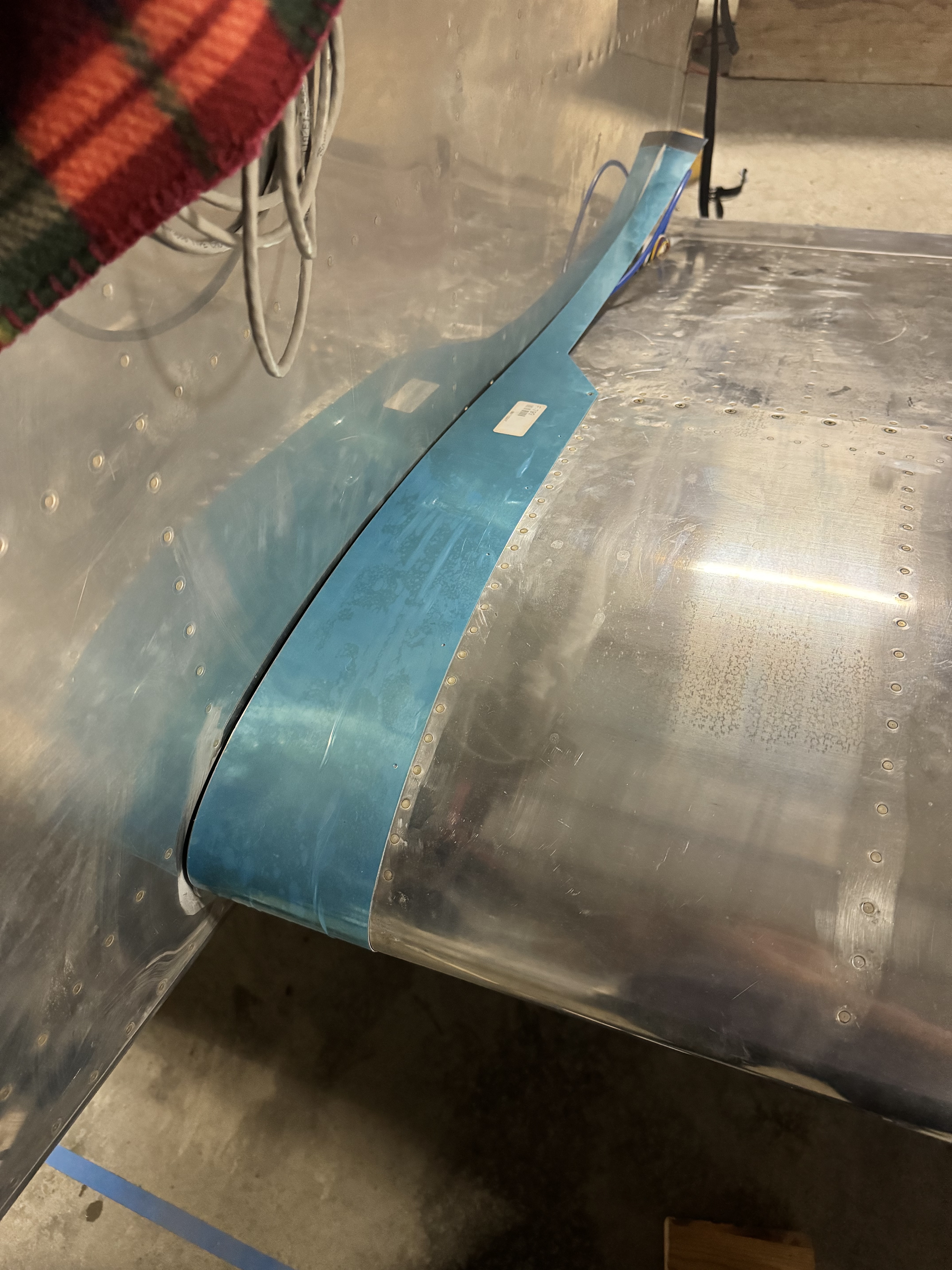
The gap between the fairings and the fuselage will be opened up to 3/16″ and then a rubber seal will be added before permanently reinstalling it.
I also recently saw a modification to the canopy installation that I really liked. Its a modification to the canopy lift struts geometry. I found it through this post (thanks Mike). It had some great guidelines, and only a slight modification was needed for my RV-7 (the post is for an RV-6).
I measured 2″ back from the panel for the forward lift brackets. The canopy brackets were 24″ back from the leading edge of the canopy frame. The struts used are Suspa 23.86″ 20lb struts. I also purchased the brackets from there as well.

The initial fitting took some trial and error, but I got it all aligned and double checked the support capabilities. The entire canopy is very well supported all throughout the closing/opening trajectory. Whats really nice about this geometry is that the canopy is supported by the struts throughout the entire cycle, but with the original geometry there is an over-center position in which the struts begin to pull the canopy down, and it is quite unstable.

Here you can see the original geometry vs the new geometry. One other big benefit to this geometry is the increased entry/exit area.

Leave a comment