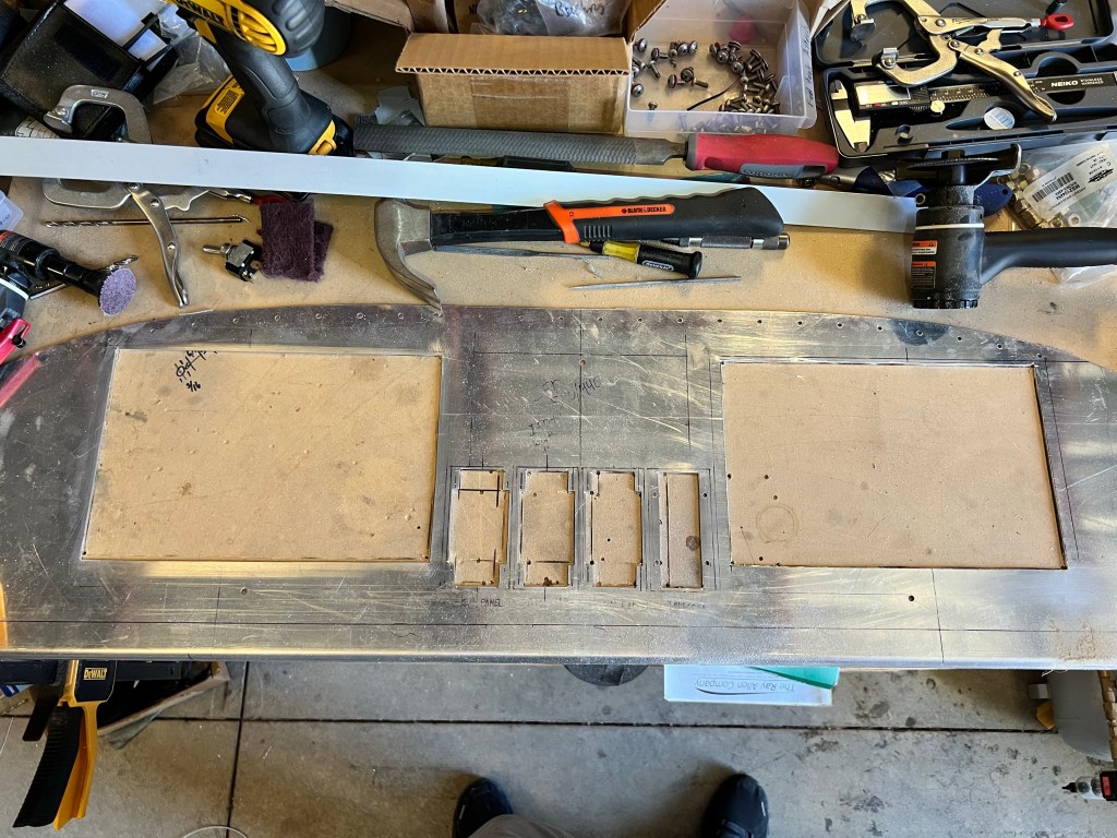
Today I cut the panel for the main EFIS screens and the sub modules. I measured and compared to the CAD probably a dozen times, and luckily it all came out straight and even.
The first thing I did was look up how much the blank RV-7 panel costs on vansaircraft.com -$40. With that knowledge, I began to cut the first sub module hole, the knob panel.
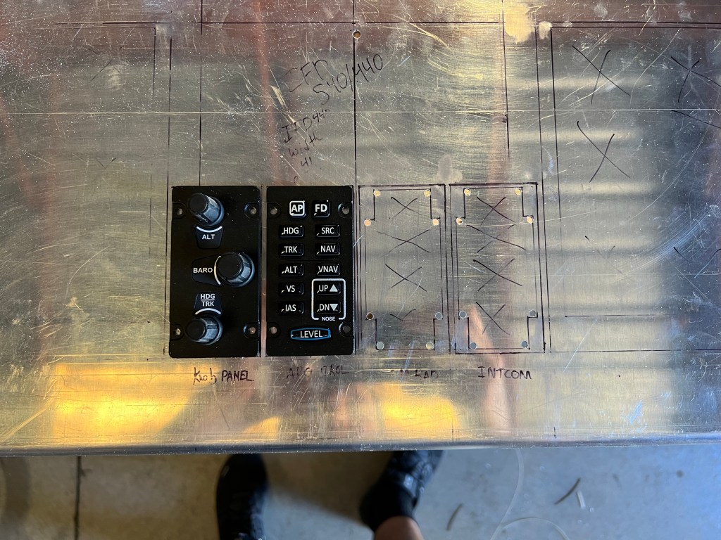
After the knob panel went smoothly I began on the second one, the AP panel. All the modules are the same dimensions, but with the variability in my hand cuts I checked and lined up each element after test fitting.
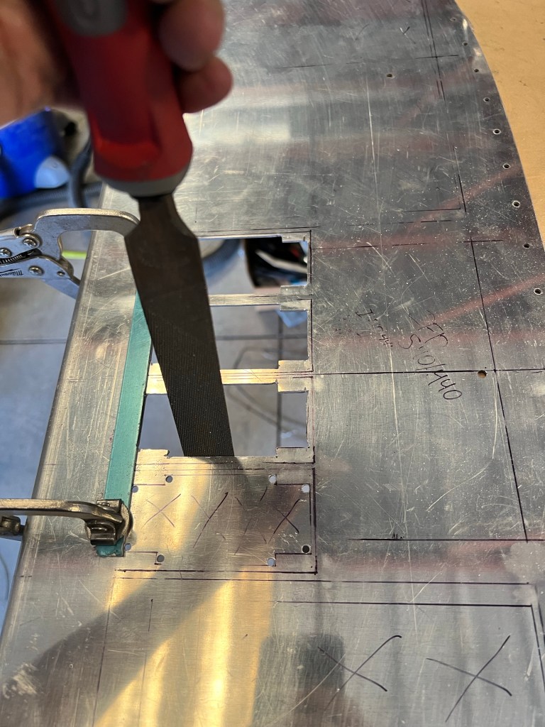
The process begins by drilling a 1/8” hole in the corners (1/16” radius). Then using a cutoff wheel I cut just inside the lines for the hole. Then I filed the edges to the final size so that each item fit perfectly, but with no catches or tight spots. Then using some scotchbright, I smoothed the edges out so they are soft to the touch.
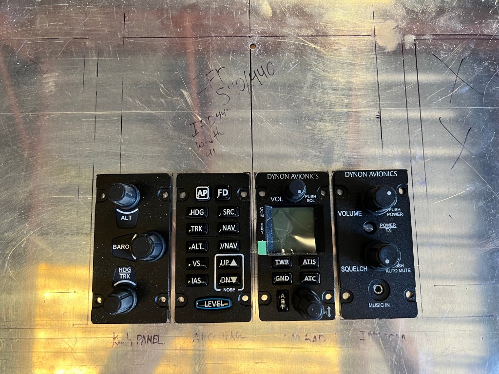
Here are the four modules sitting in the panel. I need to buy some mk2000-6 nut plates so that I can screw these to the panel.
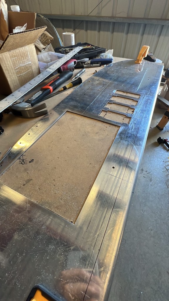
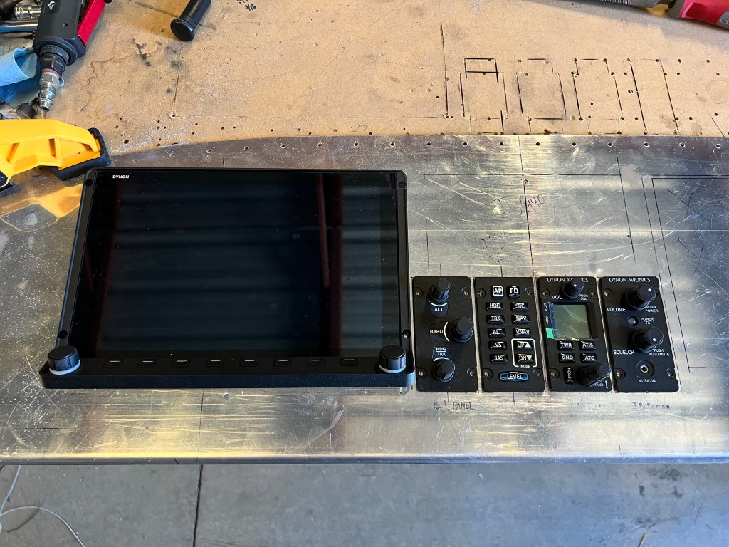
Next I cut the large hole for the main Dynon HDX displays. It was very satisfying when the display was installed. Many years to get to this point!
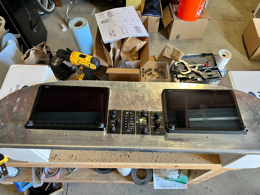
Finally I cut the second hole, making sure everything lined up and was square, and then test fit the second display.
One thing I was (and still am) a little concerned about, is the angled ledge on the displays. With the gap below being just less than 2”, I planned to install my toggle switches centered between the display and the bottom of the panel. But with the ledge of the display sticking out a bit, I might bias the switches lower to give myself a little extra room to be comfortable flipping the switches.

Once I finalize the position of the Garmin G5 I’m going to install just to the left of the pilots display, I’ll start drilling the holes for the toggle switches. I placed one just below the screen in order to see how far up and down the switch is when toggled. It should have plenty of clearance from the display.

Leave a comment